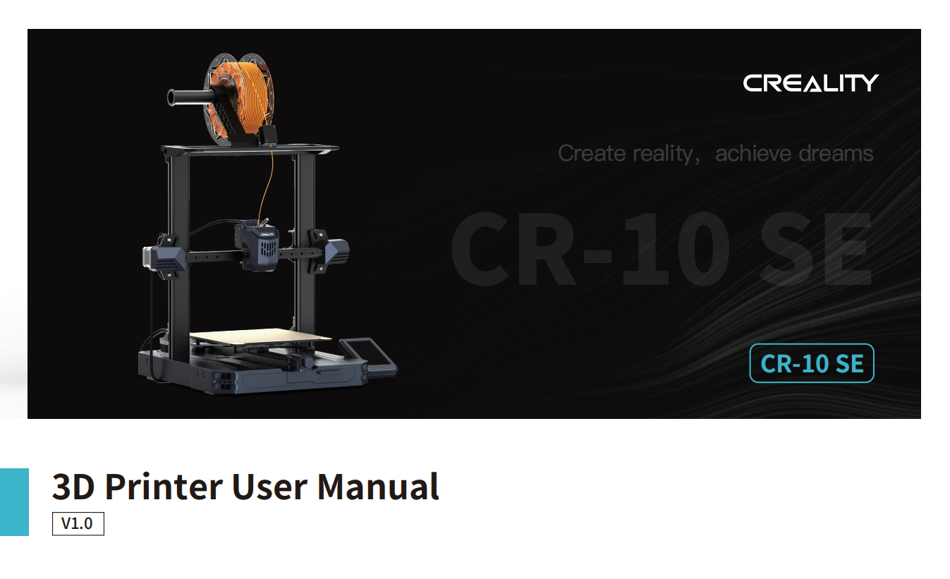
CR-10 SE User Manual
To Our Dear Users
Thank you for choosing Creality. For your convenience, please read through this User Manual before you start and follow the instructions provided carefully.
Creality is always ready to provide you with high-quality services. If you encounter any issues or have any questions when using our products, please use the contact information at the end of this manual to contact us. To further improve your user experience, you can find more about our devices via the following methods:
User manual: You can find instructions and videos in the memory card provided by the printer.
Firmware Upgrade
- To upgrade the WiFi firmware, you can upgrade the firmware via the Creality Cloud OTA;
- To upgrade the equipment firmware, you can visit https://www.creality.com, click on Service Center → Firmware/Software Download → Download the required firmware, install and use it.
Videos showing the operation of the products and after-sales service
- Please visit https://www.crealitycloud.com/product, click “Products” and select the right model, and then click “Related” to view the tutorials on after-sales service;
- Or contact our after-sales service center at +86 755 3396 5666, or send e-mail to cs@creality.com.
NOTES
- Do not use the printer in any way other than described herein in order to avoid personal injury or property damage;
- Do not place the printer near any heat source or flammable or explosive objects. We suggest placing it in a well-ventilated, cool and dustless environment;
- Do not expose the printer to a violent vibration or any other unstable environment, as this may cause poor print quality;
- Please use recommended filaments to avoid clogging of the extrusion head and causing damage to the machine;
- Do not use the power cable of other products during installation. Always use a grounded three-prong power outlet, which accompanies the printer;
- Do not touch the nozzle and the heated bed during operation to avoid burns or personal injury;
- Do not wear gloves or wraps while operating the machine to prevent entrapment of movable parts that could cause crushing and cutting injuries to bodily parts;
- Use the provided tools to clean the filament from the extruder in time taking advantage of the residual temperature after printing. Do not touch the extruder directly when cleaning, otherwise, it may cause burns;
- Clean the printer frequently. Clean the printer body with a dry cloth regularly after powering off the printer, wipe away dust, bonded print filament, and foreign objects on the guide rails;
- Children under 10 years old should not use the printer without supervision, otherwise, it may cause personal injury;
- Users should comply with the laws and regulations of the corresponding countries and regions where the equipment is located (used), abide by professional ethics, pay attention to safety obligations, and strictly prohibit the use of our products or equipment for any illegal purposes; Creality will not be responsible for any violators’ legal liability under any circumstance;
- Tip: Do not plug in or unplug wires on a charged basis.
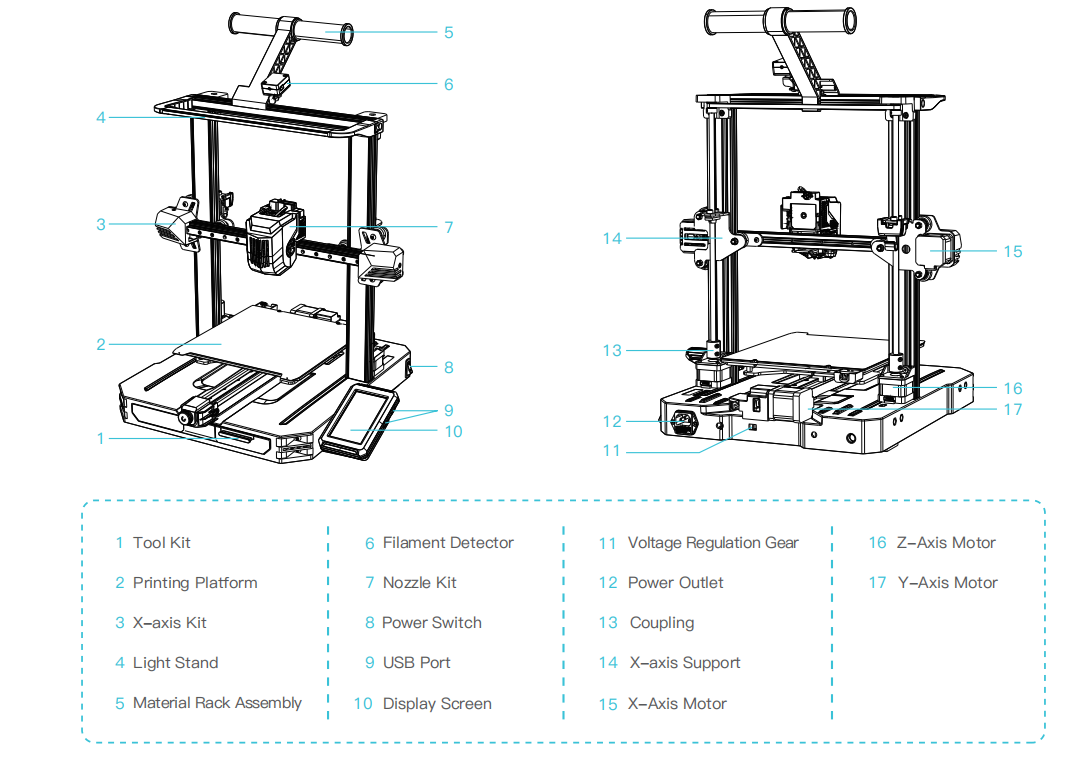
1. About the Printer
2. Parts List
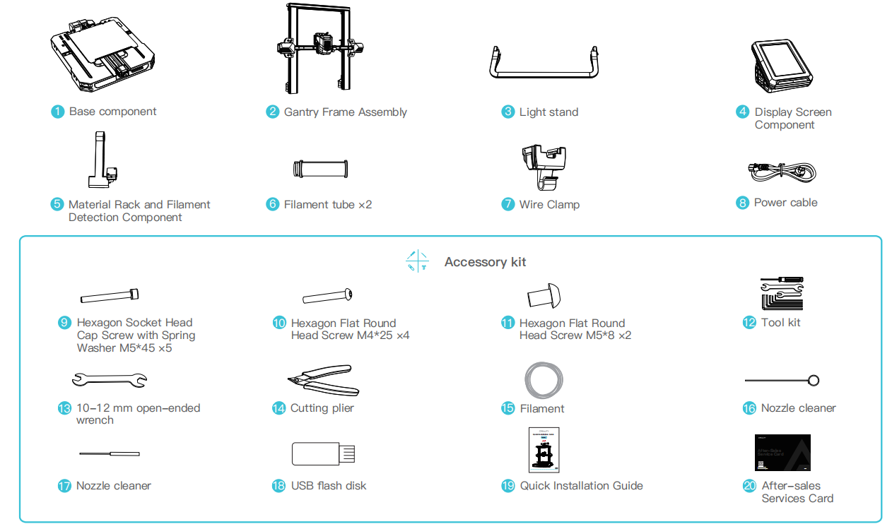
Tips: the above accessories are for reference only. Please refe r to the physical accessories.
3. Assembly Procedure
3.1 Light Stand Installation
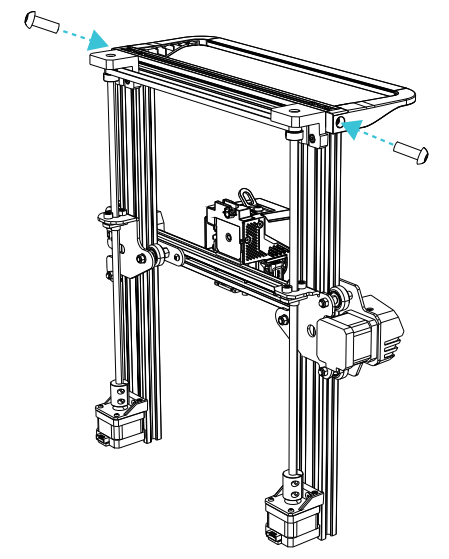
- ① Use two M5×8 screws to align and tighten the holes on the left and right of the light stand, and install the light stand on the gantry frame;

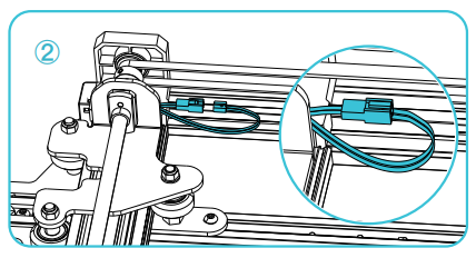
- ② Connect LED light cable;
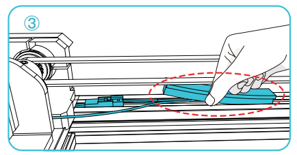
- ③ Place the LED light cable into the profile groove as shown in the diagram and secure it with sealing tape.
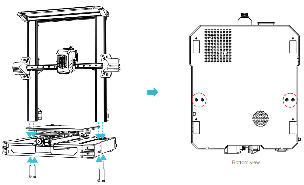
3.2 Gantry Frame Assembly Installation
Place the gantry frame assembly in the base slot and lock it using four M5x45 screws aligned with the holes from the bottom.
3.3 Display Screen Component Installation
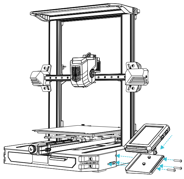
- ① Place the screen bracket on the side of the right profile, align it with the screw holes, and tighten it with three M4X25 screws;
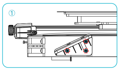
- ② Align the pins on the back of the display screen with the large hole of the screen bracket and slide it down to lock it in place;
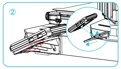
- ③ Connect the display wiring.
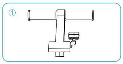
3.4 Installation of the material rack assembly and wire clip
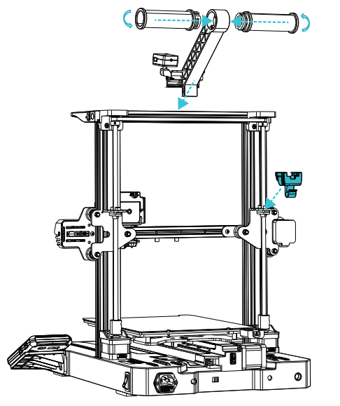
- ① Install the material rack and material barrel according to the diagram;
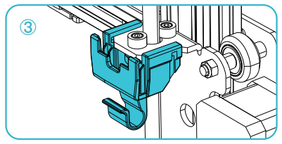
- ② Align the front slot of the installed material rack assembly with the front slot of the profile, and press it down firmly to secure the material rack assembly to the profile;
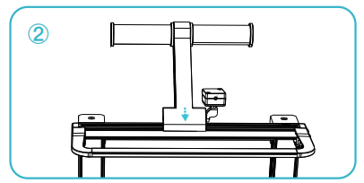
- ③ Clamp the wire clip into the back panel of the X-axis Motor.
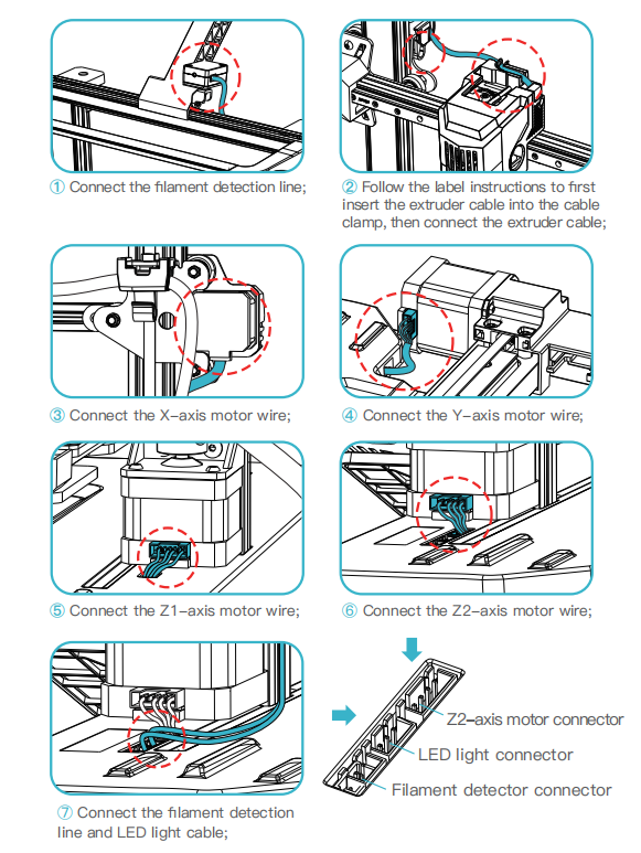
3.5 Equipment Wiring
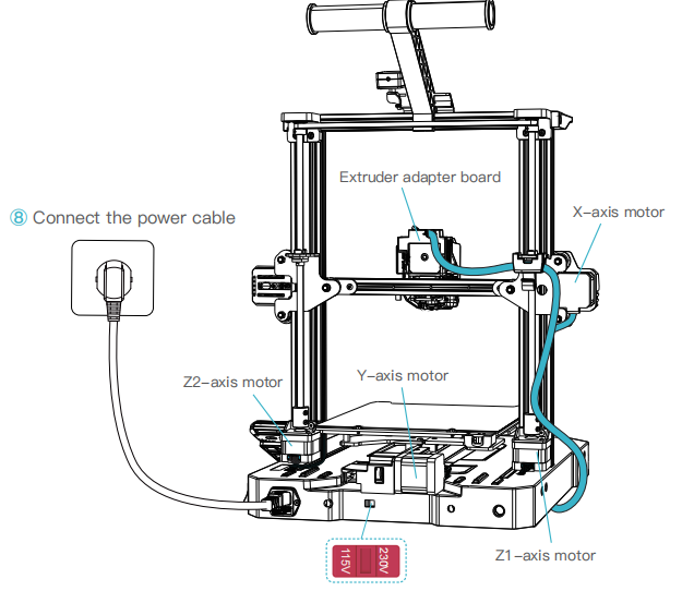
Caution:
● Please ensure the correct position for the power supply switch and mains before supply connection, in order to avoid damage to the device.
● If the mains between 100V and 120V, please select the 115V for the powersupply switch.
● If the mains between 200V and 240V, please select the 230V for the power supply switch (default is 230V).
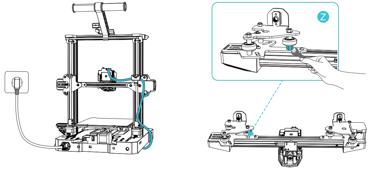
3.6 Pulley Tightness Adjustment
Before starting up, please check the tightness of the pulley.
Z axis pulley adjustment:
Gently dial the pulley to check whether it is idling or stuck. If this phenomenon occurs, use an open-end wrench to adjust the hexagonal eccentric isolation column to make it rotate smoothly.
4. About the Power-on Guide and User Interface
4.1 Power-on guide
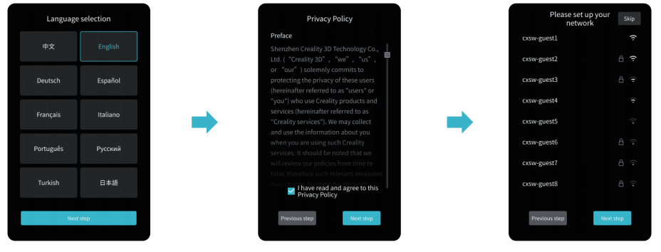
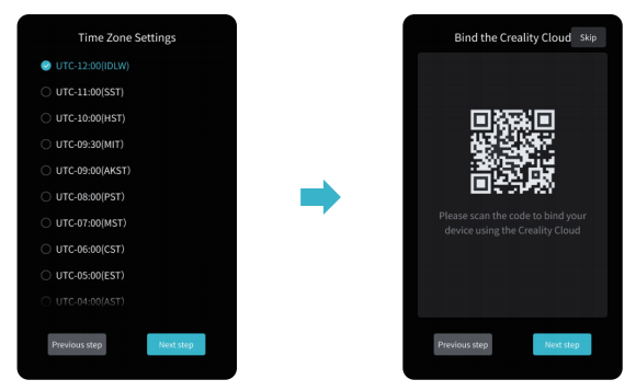
The current interface is for reference only. Due to the continuous upgrading of functions, it shall be subject to the latest software/firmware UI published on the official website.
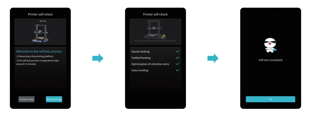
Tips:
If any abnormalities occur during the self-check process, please refer to the FAQ to check for possible machine malfunctions;Alternatively, scan the QR code for “fault reporting” to report the machine issue and seek assistance from the after-sales service for problem resolution.
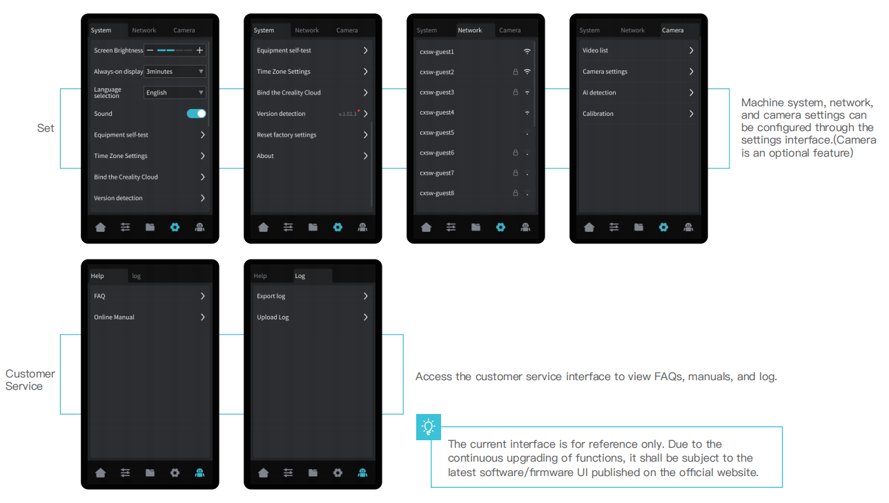
The current interface is for reference only. Due to the continuous upgrading of functions, it shall be subject to the latest software/firmware UI published on the official website.
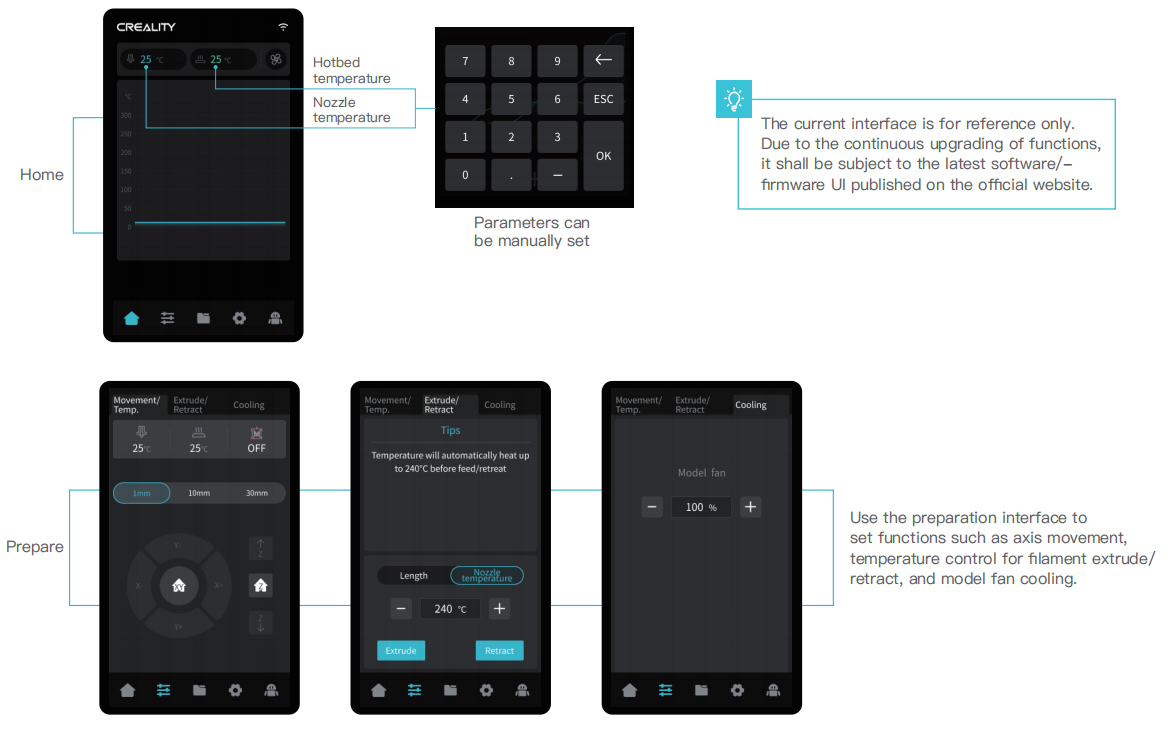
4.2 About the User Interface
5. First Printing
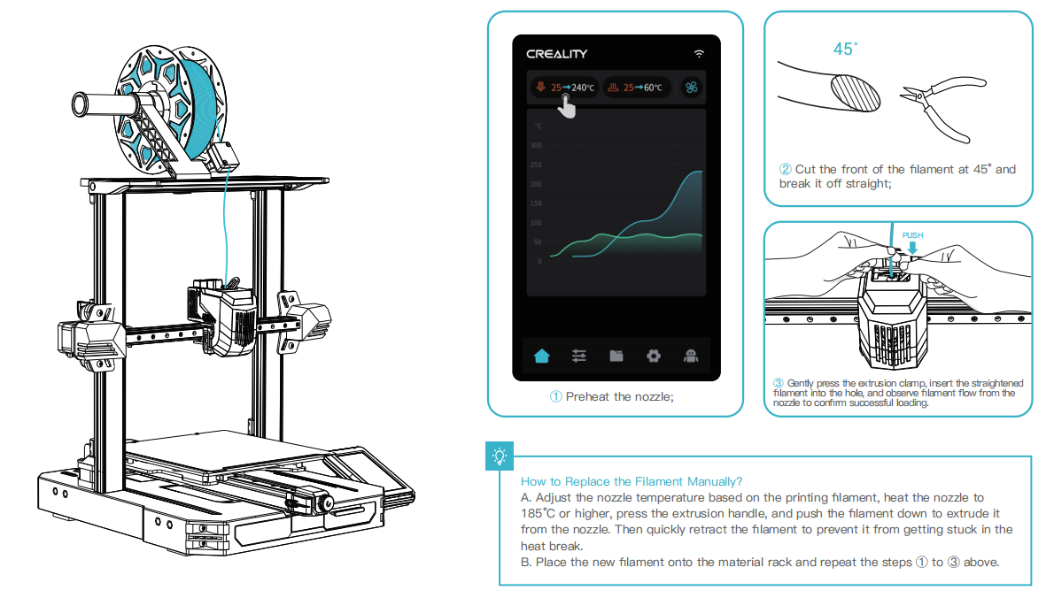
5.1 Filament Loading
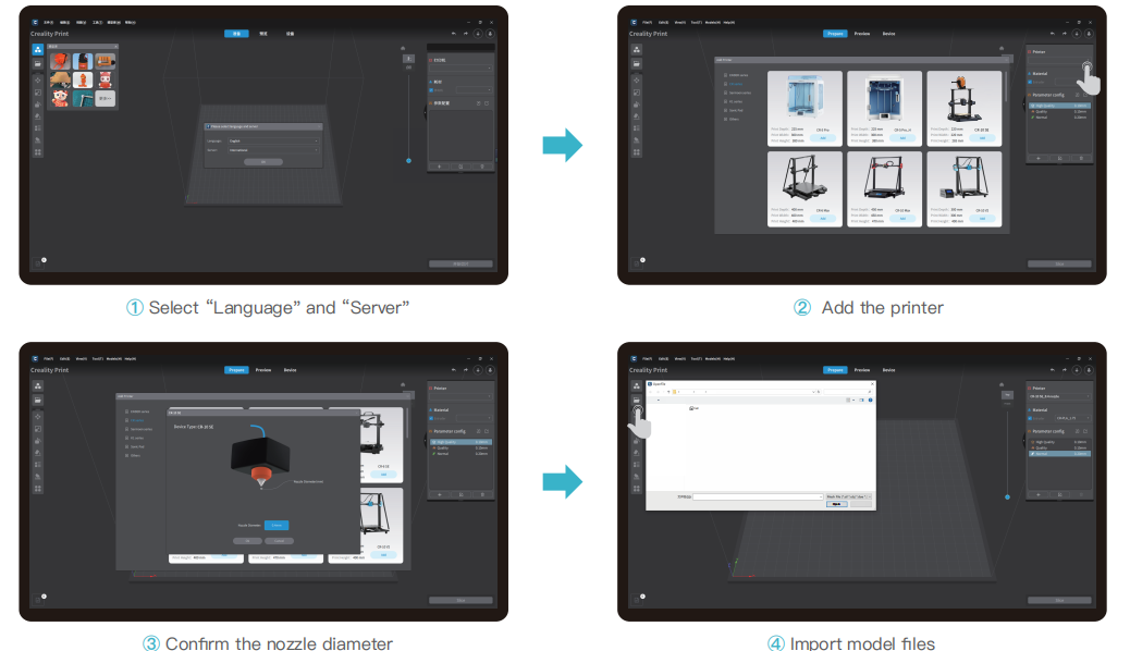
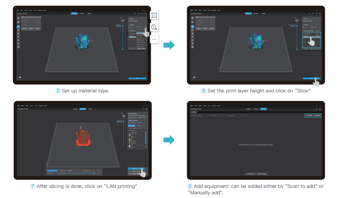
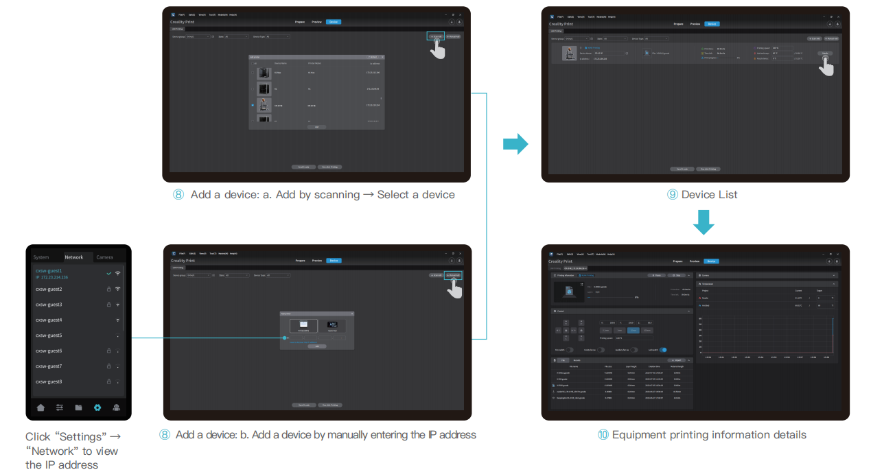
5.2 LAN printing
- ※ Install Creality Print slicing software by opening the random data on the USB flash disk.
- ※ Log in to the official website to download for installation:https://www.crealitycloud.com/software-firmware/software?type=7
The current interface is for reference only. Due to the continuous upgrading of functions, it shall be subject to the latest software/firmware UI published on the official website.
The current interface is for reference only. Due to the continuous upgrading of functions, it shall be subject to the latest software/firmware UI published on the official website.
The current interface is for reference only. Due to the continuous upgrading of functions, it shall be subject to the latest software/firmware UI published on the official website.
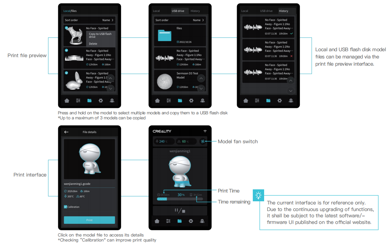
5.3 USB flash disk Printing
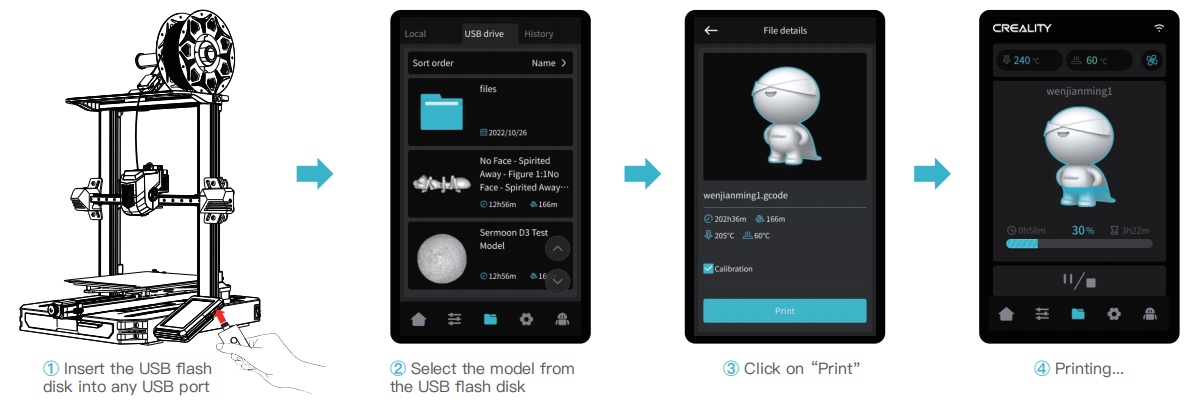
Note:
- For details on using the software, please refer to the slicing software user manual on the USB flash disk.
- Saved files must be placed in the root directory (not a subdirectory) of the USB flash disk.
- It is recommended to use Latin alphabet, numbers, and commoncharacters for the file names..
- Do not insert or remove the USB flash disk during the printing process.
The current interface is for reference only. Due to the continuous upgrading of functions, it shall be subject to the latest software/firmware UI published on the official website.
6. Functional Specification
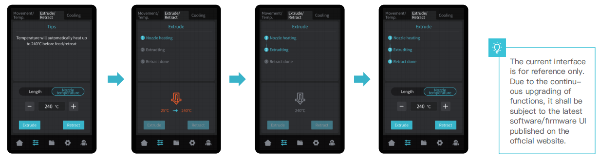
6.1 Auto extrude
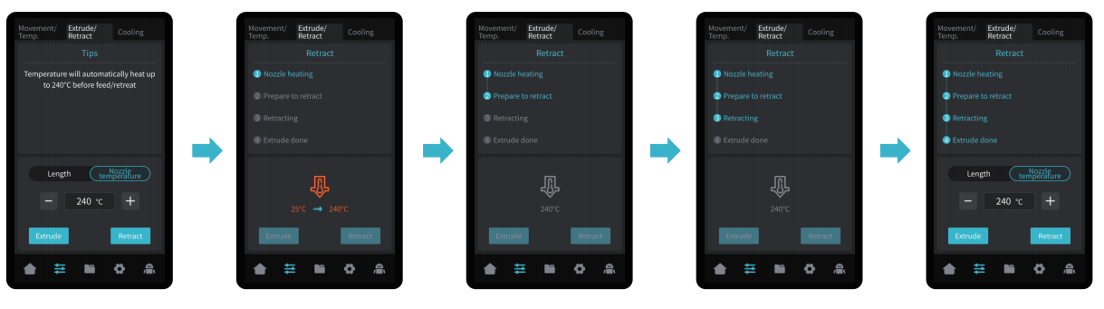
6.2 Auto retract
7. Circuit Wiring
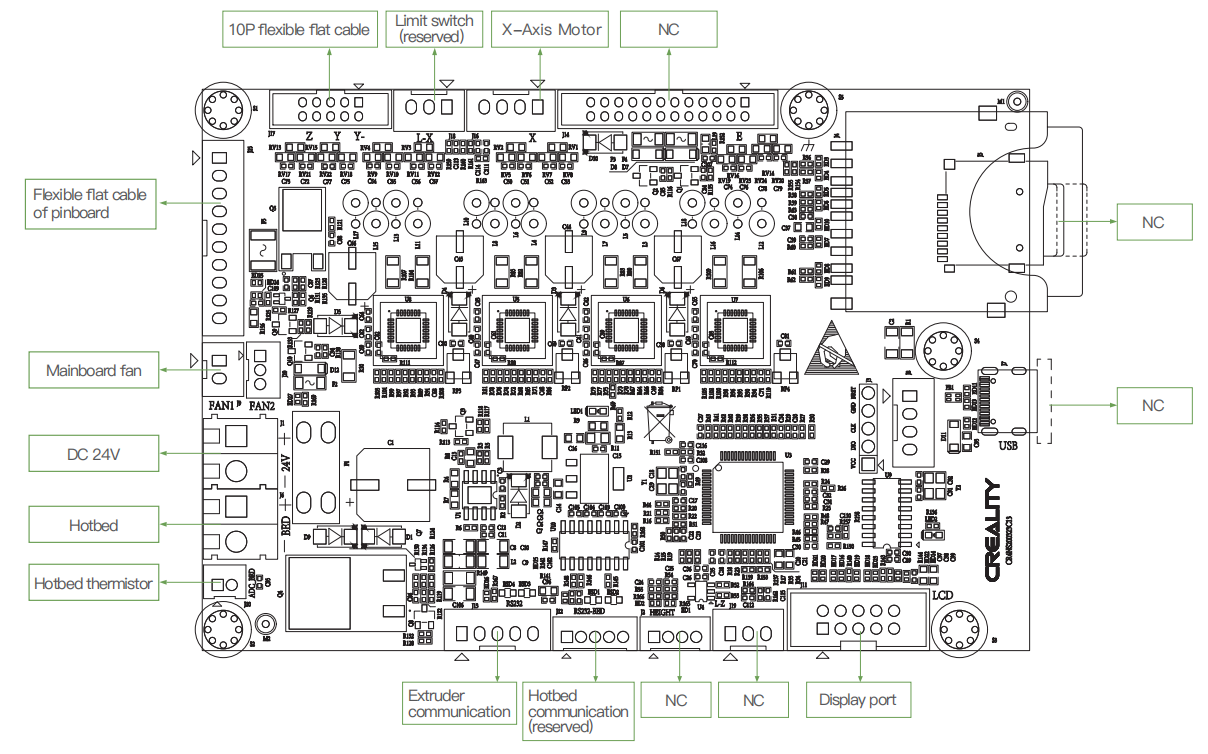
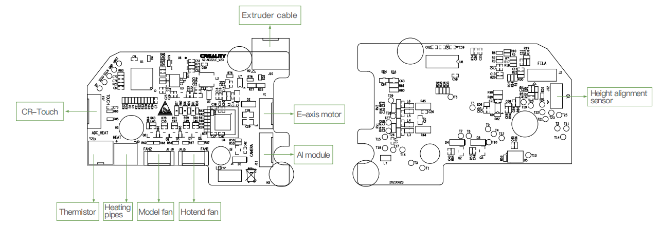
- Due to the differences between different machine models, the actual objects and the images can differ. Please refer to the actual machine.
Tips
If any of the problems arise and cannot be resolved:
- Please visit https://www.crealitycloud.com/product, click “Products” select the right model, and then click “Related” to view the tutorials on after-sales service;
- Or directly contact our after-sales service center via online service channels (See How to get the official Creality service).
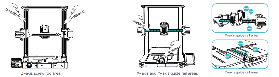
Equipment Maintenance
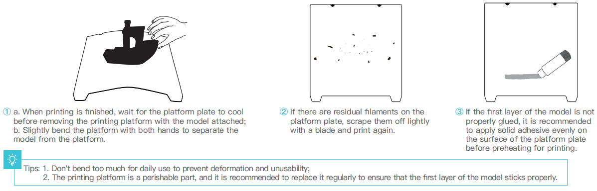
7.1 Platform plate removal and maintenance
7.2 Maintenance of screw rod and guide rail
Regularly lubricate and maintain the screw rod and guide rail areas with purchased lubricating grease.