Prior to starting off, it is important to have a basic understanding of your engraver and configure it for optimal performance to maximize your laser engraving results.
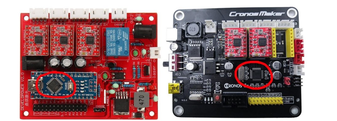
What is a Control Board?
The control board is the key component of the laser engraver. It is a small chip that runs software capable of converting g-code commands from LaserGRBL into the appropriate commands to drive the motors and regulate the laser.
LaserGRBL $$ Configuration
Named GRBL, the software can be configured using specific commands or through a user-friendly configuration window.
Connecting to your laser
To start, let’s connect the laser engraver to the computer using a USB cable. Once connected, launch the LaserGRBL and select the serial port (usually the one with the highest port number) before pressing the “connect” button. Once succeeded, the message “Grbl” with the version number (1.1h) should pop out.
If this doesn’t work, try another port or install missing drivers from the “Tools” menu. If your controller board isn’t a GRBL type(e.g. it uses BenBox or other firmware), LaserGRBL may not be compatible. In this case, you can check whether it’s possible to switch to GRBL, but that’s not the point of this document.
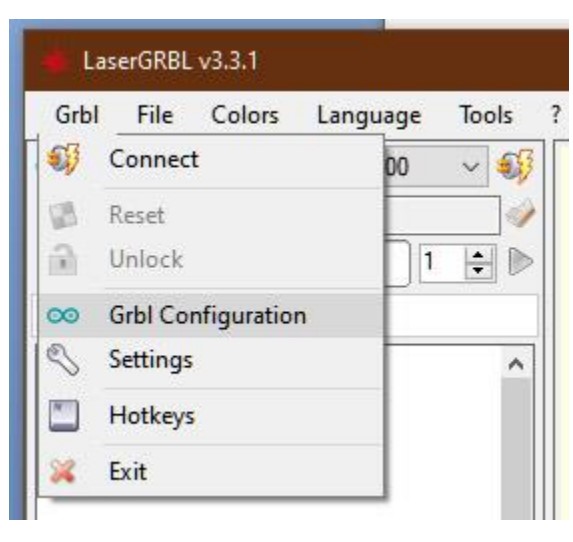
Grbl Configuration Menu
To configure GRBL, click on the “Grbl – Grbl Configuration” menu.
To access and make changes to the configuration, the laser engraver must be connected and in an inactive or “Idle” state. If it is in an “Alarm” state, connect and press the Unlock button.
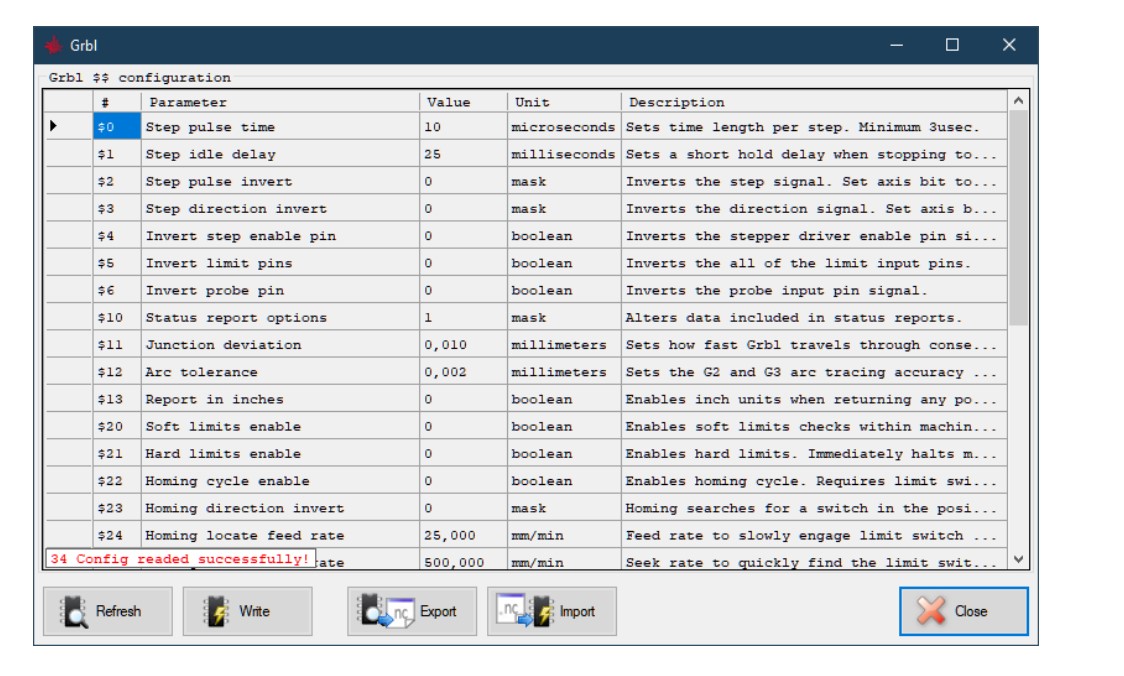
Configuration Parameters
Let’s proceed to detail the configuration parameters.
This paragraph explains, the parameters of the Grbl v1.1 version. With previous versions of GRBL, you may be missing some parameters.
$3 Parameter
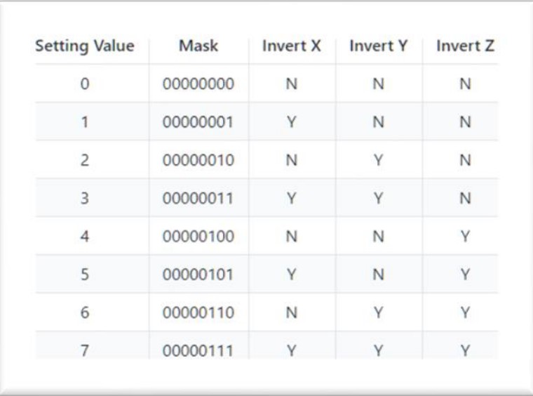
The initial parameter of interest comes to $3, which decides the direction of the axes. LaserGRBL adheres to the convention of the Cartesian plane, where X increases towards the right, Y increases away from the viewer, and Z increases upwards. If your machine operates differently, you can modify this parameter using a bit mask to invert the axes’ direction.
The table below shows that a value of 0 preserves the original orientation, while 1 inverts the X axis, 2 inverts the Y axis, and 3 inverts both X and Y axes. Configuring the axis direction Properly is crucial.
Settings and sample values
We will skip parameters $3, $4, and $5. You can learn more about their meaning below.
$10 Parameter
The $10 parameter controls the information that GRBL sends to LaserGRBL, including current location and diagnostics. For the most complete information, I suggest setting it to 3.
Skipping over $11 and $12, $13 should be set at zero to avoid unexpected behaviors in LaserGRBL, which is designed to work in mm. Parameter $20 activates software tests to prevent movements beyond the axes, requiring the correct setting of work surface dimensions ($130, $131, $132) and ensuring the laser head is in the zero position. I recommend activating this parameter by setting it to 1.
$21 to $27 Parameter
The parameters $21 to $27, also known as Hard limit and Homing, are related to limit switches that are not available on all machines but are extremely useful. They allow the machine to perform homing which involves searching for the position of the limit switches to achieve a reliable and consistent 0 position. If your machine does not have limit switches, set parameters $21 and $22 to zero. LaserGRBL will remove the homing control button and box if limit switches are absent.
$30 Parameter
$30 is one of the most confusing ones. It corresponds to the number to which GRBL will assign the code to be used to switch on the laser at max power. For example, if we assign 1000 LaserGRBL, it will send the S1000 code to turn on the laser at max power, while sending the S500 for half power. LaserGRBL will generate the S codes automatically in a manner consistent with this setting, according to the settings you specify when uploading an image, devoid of worries about what number you put.
255 appears to be the maximum number of nuances that the hardware can physically do. Another value that can have meaning is 1000 (it can be understood as 100.0%) or the value in milliwatts of your laser, for example, 4500.
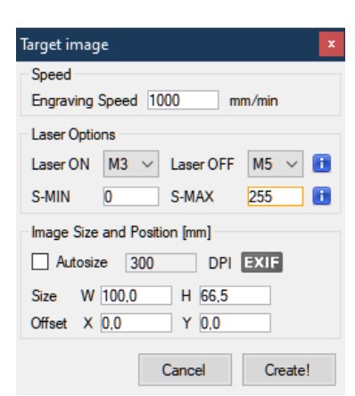
In order to achieve consistent results, it’s vital to set the S-MAX value to match the value of $30 when loading an image. For instance, if $30=255, then the S-MAX goes to 255 if you want to use the maximum laser power for BLACK. However, if your laser is too powerful and the image is too dark, you may need to lower the value a bit. As for the $31 value, it’s best to keep it at 0 since it doesn’t have much to do with the laser itself.
$32 Parameter
The $32 parameter activates the laser mode, a significant invention with respect to GRBLas the previous iterations of GRBL did not have a laser mode due to the fact that it was originally designed for CNC machines like milling cutters and lathes, which works differently from lasers. For instance, when starting milling at a specific speed, you do not have to wait for a few milliseconds for the milling cutter to reach the required RPM. However, in the case of lasers, it is possible to turn them on and off or adjust their intensity instantly.
Those who had the previous version of Grbl, or 0.9 are suggested to update to version 1.1.
Enabling or disabling Grbl’s laser mode by altering the $32 Grbl setting.
- To Enable: Send Grbl a
$32=1command. - To Disable: Send Grbl a
$32=0command.
Laser Mode also allows you to use M4 Dynamic Laser Power Mode.
This feature is one-of-a-kind as it automatically adapts the laser power to the current speed relative to the programmed rate. In other words, it ensures that the laser power remains consistent throughout the cut, whether if the machine is either at a standstill or accelerating.
$100, $101, and $102 parameters
The most important are the $100, $101, and $102 parameters. They allow you to have your work in the perfect size, exactly to the tenth of a millimeter.
These parameters regulate how many rotations steps that GRBL needs to instruct the motor to achieve a laser displacement of 1mm. However, please note that motors differ and the translation of this angle into millimeters is dependent on the varying ratios of pulleys and belts. Additionally, the “micro-stepping” value set on the driver helps to achieve resolution by enabling the motor to take intermediate steps.
If you notice that your works are not of the right size, you must therefore touch up this data. The account is very simple: if your works are twice the size you will have to halve this value, if they are half the size you will have to double it.
It is a simple proportion: $100 = $100 x Request Width / Measured Width
The values provided determine the number of steps per millimeter for the X, Y, and Z axis. If the Z axis is not applicable, the final value can be ignored.
110, $111, $112 Parameters
Parameters $110, $111, $112. These parameters determine the maximum speed at which the laser can move – without the motor blocking, tearing, or hiccups – maintaining precise and reliable positioning. If your laser is too slow, try to increase these values, and vice versa.
It is important to note that LaserGRBL will apply the highest speed setting for all rapid movements when the laser is off, such as transitioning between paths for burning. Therefore, it is crucial to set a value that allows for precise positioning but it should not be too high. While a low value may limit the speed, setting it too high can incur safety hazards. For example, if your laser’s motors work well at speeds up to 16,000 mm/min, a maximum value of 10,000 is suggested for added precaution.
Parameters like $120, $121, and $122 are also the focus of this topic as they impact the accelerations and decelerations of GRBL whenever the laser’s movement speed needs to be adjusted, such as during direction changes or when the laser comes to a stop. If the value of these parameters is set too high, the weight of the laser head and the friction in the axes could lead to losing steps of the motor or the belts slipping, resulting in imprecise positioning. On the other hand, if the value is too low, the laser may struggle to reach the desired speed as it is constantly engaged in acceleration and deceleration ramps.
$130, $131, and $132 Parameters
Finally come the parameters of $130, $131, and $132 which configure the length of the axes. The must be configured by entering the dimensions of your workable surface, that is the stroke that the laser can do in the respective dimensions.


