
Filament Not Sticking to the Bed
Relevant information
It is very important that the first layer of your print is strongly connected to the printer’s build platform so that the remainder of your part can be built on this foundation.
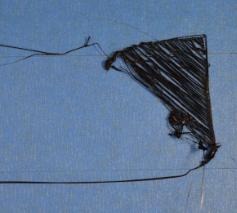
If the first layer is not sticking to the build platform, it will create problems later on. See the photo below, the first layer could not stick on the build plate. The photo below is a very classic common issue that the distance between the nozzle and the build plate was way too far, so the filament could not stick to the build plate.
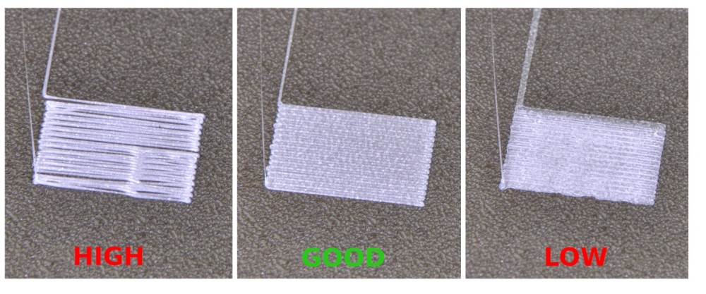
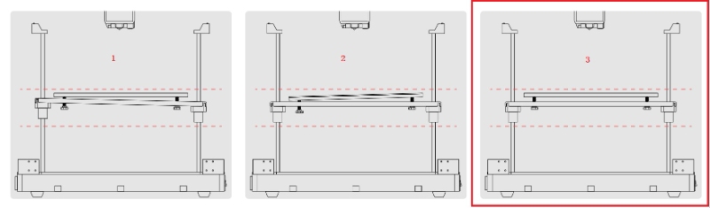
Here is the example below shows what the correct first layer should look like. The first one is too far from the bed, the second one is perfect, and the third one is too close to the bed.
 Prescription
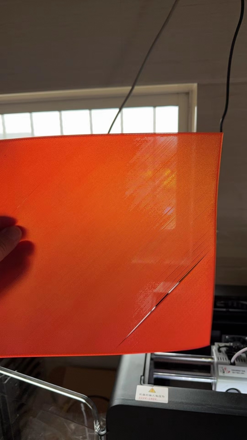
As shown in the figure below, if you encounter a gap between the first layer of lines during printing. This means that the distance between the nozzle and the build plate is too far, so you need to adjust the Z-offset of the printer. The Z-offset is the value of the distance between the nozzle and the build plate.
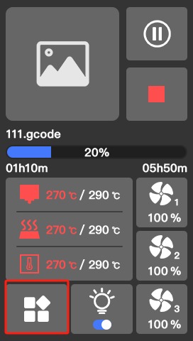
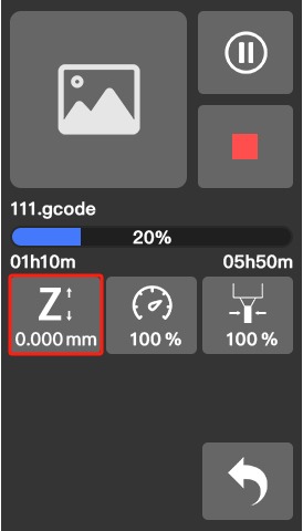
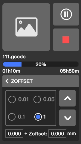
The best way to adjust the Z-offset is during the first layer printing when the print head starts to print the first layer, please click the Z-offset feature on the screen ( see the photo below, click the Z icon), after you up the build plate or lower the build plate, it will have a one-second delay, so don’t click to fast. You can start with the 0.05 value first, and see the change. The value will be saved after you adjust.
If you still can’t get a good printing result after adjustment. Please do the platform calibration.
If there is still a problem after platform calibration, please contact our after-sales staff, they will provide you with assistance.
Platform Calibration Guide
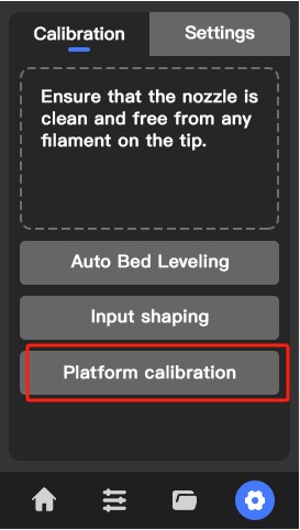
1. Click on platform calibration
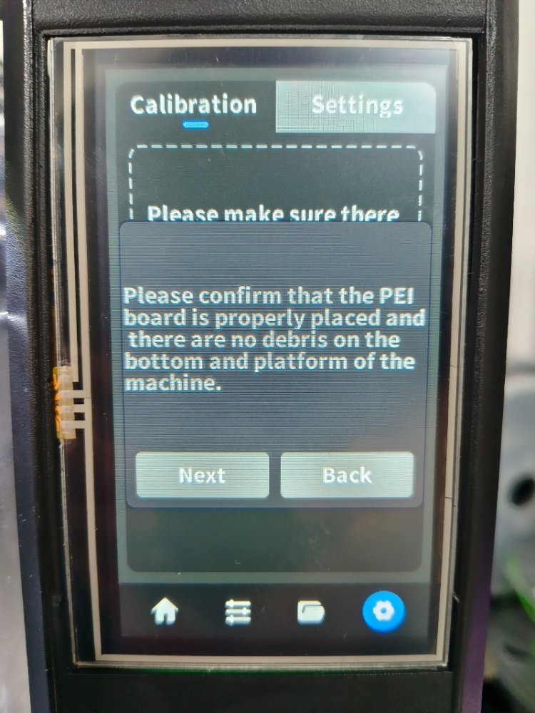
2. Preparation before calibration
Note: If 4.4.19 firmware and above, The Z-axis tilt leveling before each printing has been canceled and moved to the first step of the manual platform calibration process.
Please confirm that the PEI board is properly placed and there is no debris on the bottom and platform of the machine.
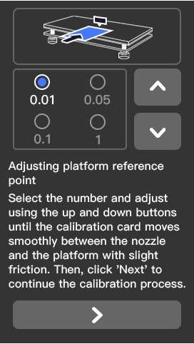
3. Adjust platform reference point height
If you don’t have a leveling card, use A4 paper instead.
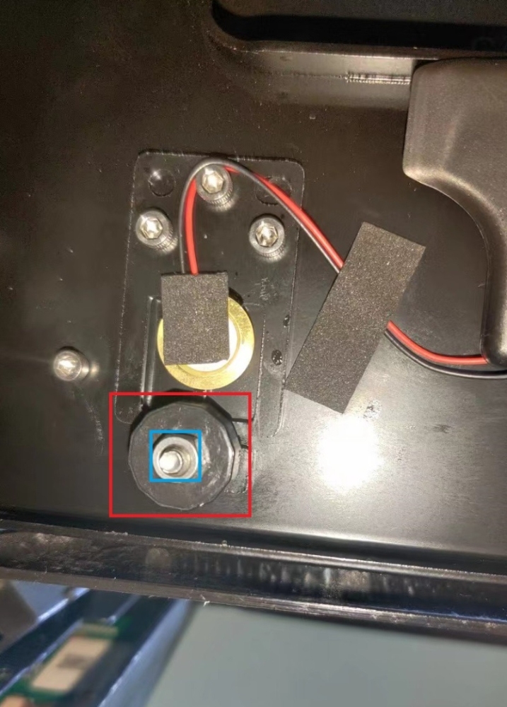
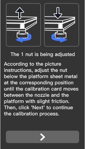
4. Adjust three platform adjustment nylon nuts (1, 2, 3)
Begin by loosening the metal locking nut (blue) located at the bottom of the hotbed. Afterward, you can adjust the three platform adjustment nylon nuts (red).
Follow the on-screen guidelines to complete the adjustment of nuts 1, 2, and 3.
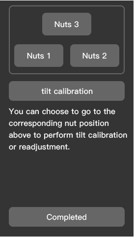
5. Finally, click completed
If further adjustment of the platform is necessary, please select the corresponding numbered platform adjustment nylon nut for adjustment.
Note: For firmware version 4.4.19 and above, there is no tilt calibration option on this page.
After the platform is calibrated, the platform is in the ideal state as shown in Figure 3.
How To Flash System Files
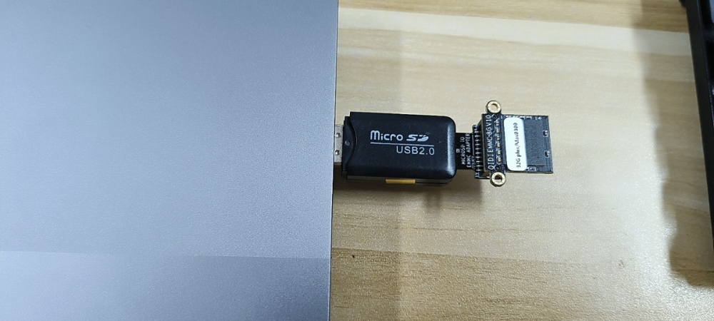
Hardware preparation
- An Emmc module not less than 8G
- EMMC-Adapter
- SD card reader
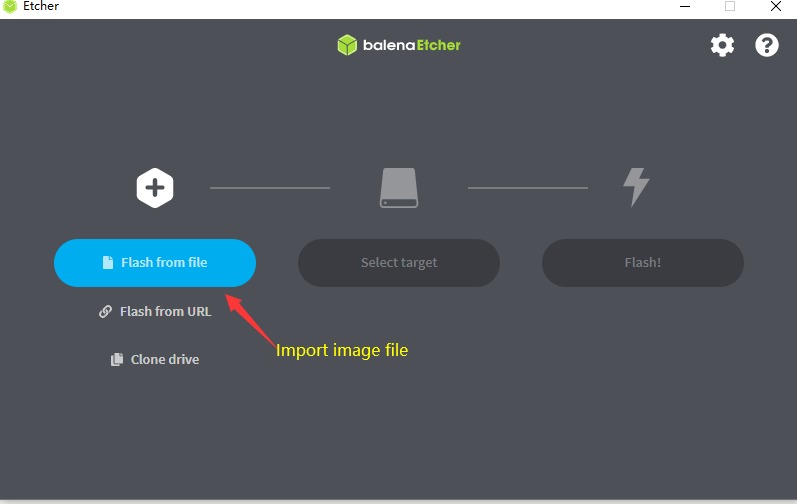
Software preparation
- Install balenaEtcher v1.5 and above, download link: https://www.balena.io/etcher/
Or you could use the Rufus, Download link: https://rufus.ie/en/
Step 1
Insert the EMMC module into the EMMC-Adapter, and insert the card reader into the PC.
Step 2
Unzip the downloaded image file
Run balenaEtcher, import the decompressed image file->Select target disk->Click to start flash
 Please update to the latest firmware after refreshing the image.
